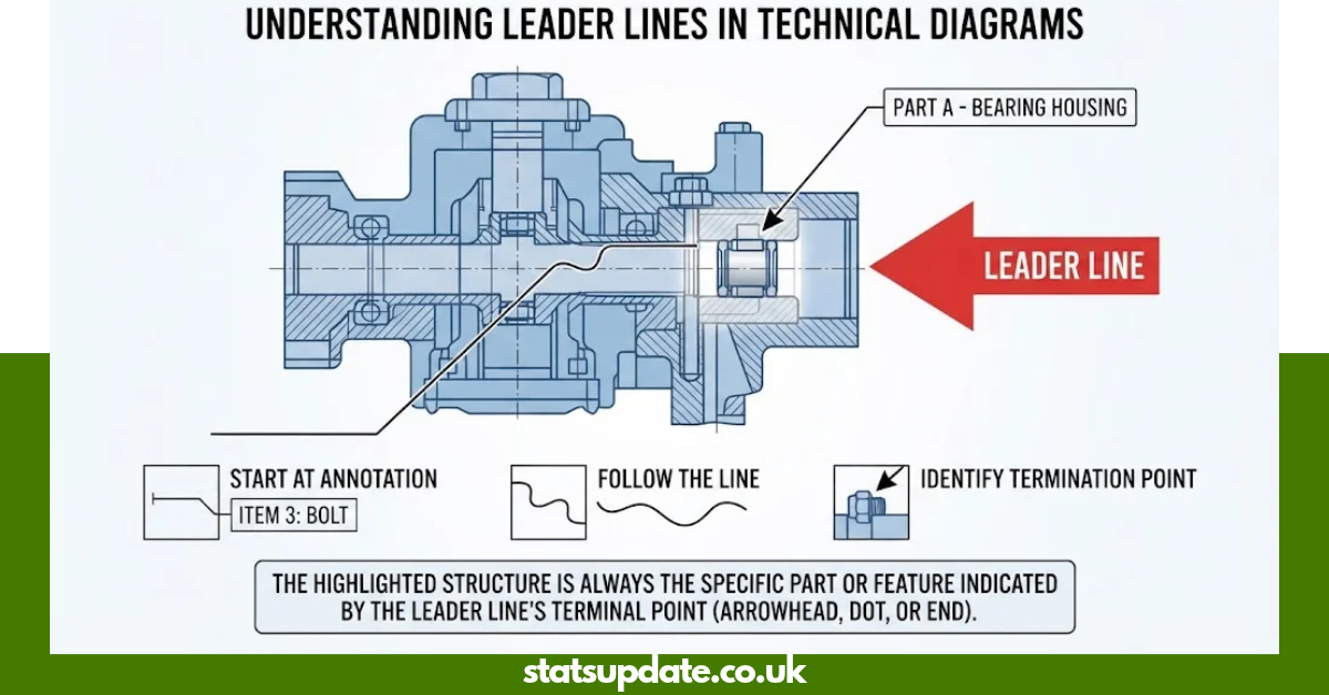
Which structure is highlighted and indicated by the leader line? The highlighted structure is the specific part, feature, or location at the point where the leader line terminates. In most diagrams, you identify it by following the leader line from its label, note, or number directly to its arrowhead, dot, or endpoint.
A leader line does not usually identify every object it crosses. It connects an annotation to one particular feature, helping the reader determine exactly which structure the label describes. Autodesk describes a leader as a line connecting annotation to a feature, while engineering-drawing guidance uses leaders to direct notes, symbols, item numbers, and part numbers to their associated features.
What Is a Leader Line?
A leader line is a thin line used to connect a label or annotation with a specific feature in a drawing or diagram. Depending on the discipline, its endpoint may include an arrowhead, dot, or another standardized termination.
In technical drawings, a leader can connect text, a symbol, a tolerance, or a part number to the feature being described. Autodesk documentation explains that a leader can begin at a point or feature and connect to an annotation.
The basic relationship is simple:
Label or annotation → leader line → endpoint → identified structure
This makes leader lines useful in engineering drawings, anatomy diagrams, biology illustrations, chemistry diagrams, architectural drawings, and assembly documentation.
Which Structure Is Highlighted and Indicated by the Leader Line?
Which structure is highlighted and indicated by the leader line? In a diagram, it is the structure directly associated with the terminal point of the leader. If the line has an arrowhead, follow the arrowhead to the feature. If it ends in a dot, the dot normally marks the referenced location.
The line itself is not normally the answer. Instead, the structure at the leader’s endpoint is the feature the annotation identifies.
For example, if a leader runs across several structures before ending at a small circular opening, the circular opening is generally the intended target. Do not select an object merely because the leader passes over it.
How to Identify the Highlighted Structure
Use this simple five-step method when answering a diagram question.
- Find the label. Locate the text, number, symbol, or annotation connected to the leader.
- Follow the line carefully. Trace the leader toward its opposite end.
- Ignore crossing objects. A leader can pass over or near other structures without identifying them.
- Find the endpoint. Look for the arrowhead, dot, or exact termination point.
- Name the structure at that point. Use the most specific accepted name for the feature.
This method works because leader lines are designed to establish a visual connection between an annotation and its associated feature. McGill University notes that assembly drawings use leader lines with arrows to point to the relevant parts.
Why the Leader Line Endpoint Matters
Which structure is highlighted and indicated by the leader line? The endpoint matters because it establishes the exact relationship between the annotation and the drawing.
A diagram can contain many nearby structures. Without a precise pointer, a label could appear to describe several possible features. The leader removes that uncertainty by directing the reader to a particular location.
In engineering drawings, leader lines may identify notes, dimensions, symbols, item numbers, and part numbers. ASME’s Y14.2 standard specifically addresses line conventions and lettering used in engineering drawings.
Leader Lines in Anatomy and Biology Diagrams
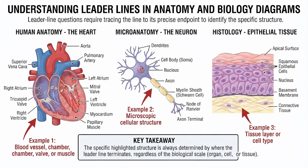
Leader-line questions are especially common in anatomy and biology study materials. A diagram may show a body part, organ, tissue, cell, or microscopic structure with several labels placed around the image.
The correct approach remains the same: trace the leader to its endpoint.
For example, an anatomy illustration could have labels pointing toward:
- A blood vessel
- A muscle
- A bone
- A nerve
- An organ
- A gland
- A tissue layer
- A chamber or opening
- A microscopic structure
The exact answer depends on the diagram. There is no universal anatomical structure represented by the phrase “which structure is highlighted and indicated by the leader line?”
If the original image is unavailable, the question alone cannot establish the name of a specific anatomical structure.
Leader Lines in Engineering Drawings
Engineering drawings use leader lines to connect annotations with physical features or components. They can identify holes, surfaces, fasteners, materials, manufacturing requirements, and individual assembly parts.
For example, an assembly drawing may use a numbered balloon connected by a leader to a component. The number then corresponds to a parts list or bill of materials. McGill’s engineering design guidance describes this method for identifying components in assembly drawings.
Autodesk also documents leaders as annotation objects that connect information with drawing features.
Common Engineering Uses
| Leader-line use | What it identifies |
| Part number | A specific component |
| Note | A feature or instruction |
| Symbol | A specified drawing feature |
| Tolerance | A feature controlled by the tolerance |
| Material note | The relevant component or surface |
| Hole callout | A hole or related feature |
| Surface note | A particular surface |
| Assembly balloon | An item in the assembly |
This is why correctly reading the endpoint is essential when interpreting technical drawings.
Leader Line vs. Dimension Line
A common mistake is confusing a leader line with a dimension line.
A dimension line communicates a measurement such as length, diameter, radius, or distance. A leader line connects an annotation to a feature or location.
| Feature | Leader Line | Dimension Line |
| Main purpose | Identify or reference a feature | Show a measurement |
| Typical connection | Label to feature | Between extension lines |
| Common content | Note, symbol, part number | Numeric dimension |
| Endpoint | Arrow, dot, or defined termination | Usually arrowheads |
| Main question answered | “What feature does this note describe?” | “How large or far is it?” |
ASME’s line-convention material distinguishes dimension, extension, and leader lines by their functions.
Leader Line vs. Extension Line
An extension line also has a different purpose.
An extension line extends from a feature so that a dimension can be clearly associated with that feature. It helps establish the limits of the measurement.
A leader line, on the other hand, directs an annotation toward a particular feature.
A useful memory trick is:
- Leader = identifies
- Dimension = measures
- Extension = extends the feature boundary for measurement
Understanding this distinction can prevent errors when interpreting engineering diagrams.
What Does the Arrowhead Tell You?
Which structure is highlighted and indicated by the leader line? When a leader has an arrowhead, the arrowhead usually provides the strongest visual clue about the intended feature.
Look closely at where the arrowhead touches or points. The target may be:
- The edge of an object
- The center of a feature
- A specific surface
- A hole
- A component
- A line or boundary
- A particular region of a diagram
Do not automatically choose the largest structure near the arrow. Identify the exact point referenced by the arrowhead.
Autodesk’s documentation confirms that leader objects can use arrowheads and that the leader connects annotation with a feature in the drawing.
What If the Leader Line Ends With a Dot?
Some diagrams use a dot instead of an arrowhead. In that situation, the dot itself marks the referenced location.
This matters when the target is a surface, region, or small feature rather than a broad object. The reader should identify what lies exactly underneath or at the marked point.
The visual convention can vary between educational diagrams and technical standards, so the diagram’s legend or accompanying instructions should take priority when available.
What If the Leader Line Crosses Another Structure?
A crossing does not automatically mean the leader identifies the structure it crosses.
This is one of the most important rules for solving leader-line questions.
Suppose a leader travels across a large organ and eventually points to a small structure near its edge. The large organ is not necessarily the answer. The endpoint determines the intended target.
Engineering drawing guidance emphasizes keeping leader lines clear and avoiding unnecessary intersections because clarity is important when identifying parts.
Common Mistakes When Reading a Leader Line
Which structure is highlighted and indicated by the leader line? Many incorrect answers happen because the reader interprets the visual path instead of the endpoint.
Mistake 1: Choosing the Structure the Line Crosses
A leader may pass across several objects before reaching its target.
Fix: Follow the line until it ends.
Mistake 2: Looking Only at the Label
The label tells you what is being described, but its position alone does not identify the structure.
Fix: Trace the connected leader.
Mistake 3: Ignoring the Arrowhead
A small arrowhead can be easy to miss in a crowded diagram.
Fix: Zoom in and inspect the endpoint carefully.
Mistake 4: Guessing From the Diagram Topic
Knowing that an image shows the heart, cell, machine, or skeletal system does not automatically reveal the answer.
Fix: Use the leader’s exact endpoint as your primary clue.
Mistake 5: Assuming Every Diagram Uses the Same Convention
Educational diagrams can differ from formal engineering drawings.
Fix: Check the legend, instructions, or standard associated with the specific diagram.
A Fast Method for Quiz and Exam Questions
When time is limited, use this quick process:
Label → Trace → Endpoint → Structure → Verify
Step 1: Locate the label
Find the question’s label, number, or annotation.
Step 2: Trace the leader
Move your eyes along the entire line rather than jumping to the nearest object.
Step 3: Locate the endpoint
Identify the arrowhead, dot, or termination.
Step 4: Name the structure
Choose the precise feature indicated by the endpoint.
Step 5: Verify
Check whether the selected structure matches the diagram’s terminology and context.
This approach is faster and more reliable than guessing based on position.
Complete Guide to Leader-Line Interpretation
| Question | Correct approach |
| What does a leader line identify? | A specific feature or location connected to an annotation |
| Where should you look first? | At the label or annotation |
| Where should you trace next? | Along the leader toward its endpoint |
| What usually marks the target? | Arrowhead, dot, or defined termination |
| Does a crossing object become the target? | No, not simply because the line crosses it |
| Can leaders identify parts? | Yes |
| Can leaders identify notes or symbols? | Yes |
| Are leaders used in engineering? | Yes |
| Are leaders used in anatomy diagrams? | Yes |
| Can the exact answer be known without the diagram? | Not if the question asks for a specific structure |
| What is the most important clue? | The leader’s endpoint |
How Digital Drawing Software Uses Leader Lines
Modern drafting programs such as AutoCAD provide dedicated leader and multileader tools. These tools connect annotation with drawing features and can include text, symbols, arrowheads, and other annotation elements.
Autodesk’s current documentation also explains that leader settings can control features such as the leader-line format, arrowhead, attachment location, and number of leader points.
This matters because digital drawings may contain several leader styles. The underlying purpose remains consistent: connect explanatory information to the feature it describes.
How to Answer “Which Structure Is Highlighted?” From an Image
If you receive a diagram containing a leader line, use this checklist:
- Find the question’s label.
- Locate the connected leader.
- Follow it without skipping any segment.
- Inspect the arrowhead or endpoint.
- Identify the exact structure at that point.
- Compare the feature with nearby structures.
- Use the diagram’s terminology where possible.
- Avoid guessing when the image is unclear.
- If necessary, zoom into the endpoint.
- Give the specific structure rather than a broad category.
If the image is blurry or cropped, the safest approach is to obtain a clearer version rather than inventing an answer.
Why Leader Lines Improve Diagram Clarity
A good diagram must communicate relationships quickly. Leader lines reduce ambiguity by creating a direct visual path between explanatory information and the relevant feature.
This is especially important in complex technical drawings containing many components. McGill’s engineering design guidance recommends clear leader placement and notes that leaders should generally remain short and avoid unnecessary intersections.
ASME’s Y14 standards provide broader conventions for engineering drawing communication, including line practices used in technical documentation.
Expert Tip: Focus on the Point, Not the Path
Which structure is highlighted and indicated by the leader line? The strongest clue is normally the point of termination, not the route taken by the line.
Imagine the leader as a pointer rather than a boundary. Its path simply connects the label to the target. The final point tells you where to look.
This single habit can make anatomy quizzes, biology diagrams, engineering drawings, and technical illustrations much easier to interpret.
Frequently Asked Questions
The indicated structure is normally the feature at the leader line’s endpoint. Follow the line from the label to its arrowhead, dot, or termination, then identify the structure located there.
A leader line connects an annotation to a specific feature in a diagram or technical drawing. It can identify a part, surface, symbol, note, dimension, or other referenced feature.
No. A leader can pass near or across other structures while pointing to one specific target. The endpoint normally provides the key identification.
Start at the label and carefully trace the leader to its endpoint. Then identify the anatomical structure at that exact location. Without the original diagram, the phrase alone cannot determine a specific anatomical structure.
No. Leader lines appear in many types of diagrams, including engineering, anatomy, biology, chemistry, architecture, and educational illustrations. Their exact visual conventions can vary by application.
Zoom in on the endpoint, check the diagram legend, and compare the target with nearby structures. If the image remains unclear, use a higher-resolution version instead of guessing.
Conclusion
Which structure is highlighted and indicated by the leader line? The answer is generally the specific structure or feature at the leader line’s endpoint. Start at the label, trace the line carefully, ignore objects it merely crosses, and identify the feature marked by the arrowhead, dot, or final termination.
This simple technique works across technical drawings, anatomy diagrams, biology illustrations, and many educational questions. When a diagram is available, the endpoint provides the strongest evidence; when the image is missing, a precise structure cannot be identified reliably from the question alone.